Description
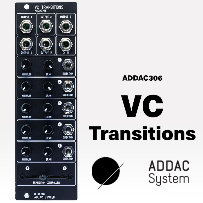
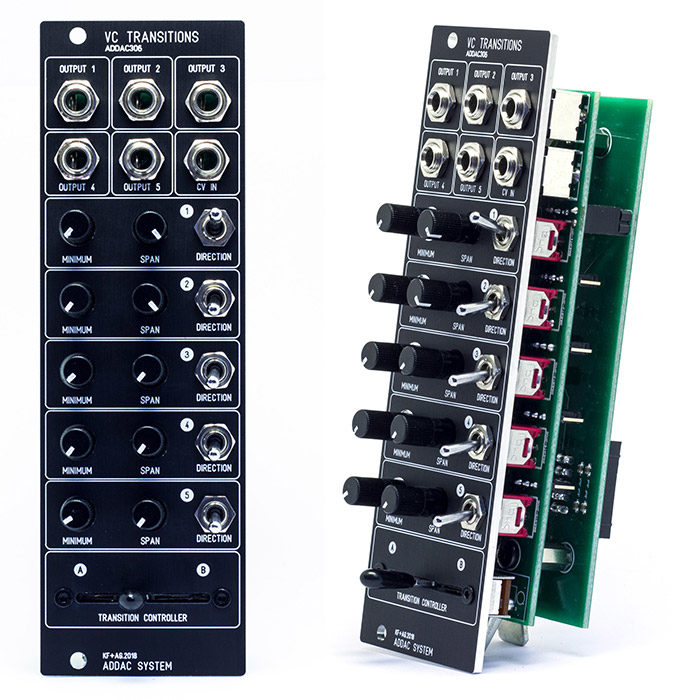
The ADDAC306 is a 5 channel multi-directional CV generator – you can think of it as a “sweet spot” controller, or a hands-on way of transitioning from one state to another. Each of the five channels has MINIMUM, SPAN and DIRECTION controls, a common CV IN and a common TRANSITION CONTROLLER slider.
Controls
- MINIMUM sets the minimum channel voltage.
- SPAN sets the voltage range of the channel. It essentially sets the maximum voltage that can be output from the channel, relative to what the current channel MINIMUM is. For a given SPAN value, if the MINIMUM voltage is changed then the maximum voltage output from that channel will also change respectively.
- DIRECTION sets whether the voltage transition for each channel goes from MINIMUM to maximum, or maximum to MINIMUM.
- The TRANSITION CONTROLLER slider controls the transition from the minimum value (A) to the maximum value (B) or vice versa, according to the settings of each independent channel.
- Moving this slider generates 5 different voltages with 5 different ranges and directions. The transition can also be operated from a CV source at the CV IN, in which case the slider position acts as an attenuator for the incoming voltage.
The maximum range of each channel can be set to either 5 or 10 volts, by 5 jumpers in the back of the module. Only positive voltages are generated at the output. See the settings examples here
Patch Ideas
- Using the CV IN you can use two ADDAC306 modules to expand your control options to 9 voltage outputs under one common slider control.
- Use the VC Transitions to multiply the polyphony of a single CV sequencer by passing its outputs through the ADDAC207.
- VC Transition makes for an awesome state transition controller. Plug its outputs to various CV controller parameters of your audio effects modules. Set the slider to position A, and set the minimum values for each channel. Then move the slider to position B and set the SPAN settings for each channel. Use the TRANSITION CONTROLLER slider to morph from state A to state B and backwards. Flip the DIRECTION switches to change the direction of the transition for each channel. Use the CV IN to automate the transition using LFOs, ADSRs or sequencers.
- Plug the output of your ADSR envelope to the CV IN and set the channels differently to get 5 different ADSRs from one common source.
Specs:
- Width: 8HP
- Depth: 40mm
- Max current: 50mA +12V, 50mA -12V,
Build Document – Assembly Guide

