Description
The design of CLOT is based on an original idea by Jan Hall, firstl published in Electronotes EN 92 page 14-15 then refined and published as a manufactured PCB by Ken Stone as the “Bi-N-Tic” filter . Ken Stone kindly gave permission to use his design as a starting point for this module.
Djupviks have twisted the original circuits and transformed them into a misbehaving monster! The core principle is the same: an internal (or external) VCO drives two analog switches which bounce between two banks of eight capacitors. In the original layouts the capacitors are all the same value, but using completely different values is what makes this “filter” get more unusual. Djupviks have also added switches for regulating the tempo and offset filter frequency pots and some logic.
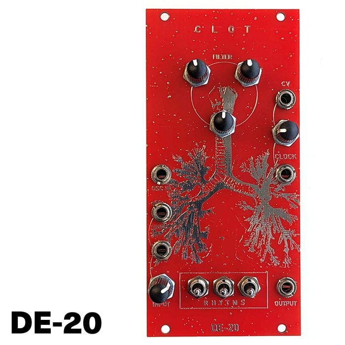
The filter sections has the usual controls of frequency and Q/resonance (or damp). Another update from the original design is that there are now 2 x independent controls for filter frequency instead of one, allowing for the creation of even more chaotic sounds when these controls are offset from each other. Ken writes: “Not all combinations of these two are actually valid, some resulting in silence, but none the less, quite an array of variations is possible” this is even more true with CLOT.
On the left side of the module is an input for an external VCO to override the internal oscillator. This is largely to drive the clock of this filter with a more precise 1v/per octave oscillator (Like the Dual Bristol Bloodhound) which works well when sequenced to create interesting effects like flanging sounds etc. with the filter. Below this are 2 x inputs for sound sources, the bottom one has an attenuator connected to it and the pulses from the analog switches are normalled (through some logic) into this input for pinging action or accentuation of the “tempo” of the filter. The associated knob lets you dial in how much of that you want present. Of course this can also be used to mix a second incoming signal into the filter and control the volume of the input.
In the middle you have the 3 switches alternating the tempo, ie – what pulses from the analog switches are sent to the switching capacitors. These are (just like on HEALTH) labeled “Rhythms” because usually this creates different rhythms also present at the clock output.
On the right of the module there’s an onboard clock oscillator with CV control, the knob attached to the cv input is the tempo (with no signal plugged into the cv input) with a cv inserted it acts as an attenuator for the incoming signal. The jack below labelled “Clock” is an output with some AND-gate logic attached to it. At very high speeds you’ll have a droning square wave oscillator present here, while at lower speeds you can use this output to clock other modules. The main filter output is at the bottom right of the module.
DE-20 – Build Document & User Guide
All SMD parts are already pre-soldered