Description
ENTROPY
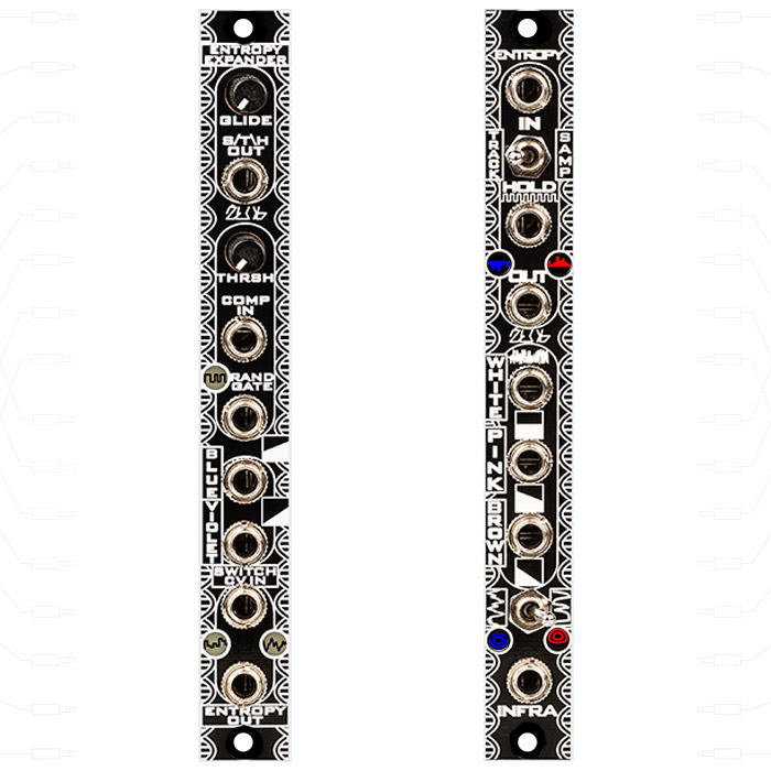
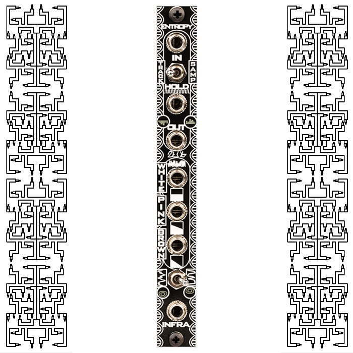
Entropy is an all analog random voltage and noise generator with a number of outputs and options. It features sample/track and hold normalled to white noise with a toggle switch for selecting either Sample & Hold (switch in right position) or Track & Hold (switch in left position). There is also a PCB trimmer to adjust the spread or gain of random voltages coming out of the module. This ranges from “scalar” (low gain, counter clock wise) to large interval jumping (high gain, clock wise).
Entropy also features dedicated outputs for analog white, pink, and brown (red) noise as well as a separate smooth random (INFRA) output with 2 range settings – with the switch in its left position, events will be quicker and more “wiggley”, while in the right position there will be less events and almost random rise and fall envelope behaviour. There is a white noise PCB trimmer to set the amplitude of the noise which in turn influences the rate of the INFRA out.
The aluminium Frontpanel has LED solder mask windows to indicate positive(red) and negative(blue) voltage crossings
Entropy – Assembly Guide
Specs:
- Width: 3HP
- Depth: 47mm
- 10vpp~ Noise Outputs (dependent on white gain trim)
- current consumption +12v: 10mA -12v: 10mA
ENTROPY EXPANDER
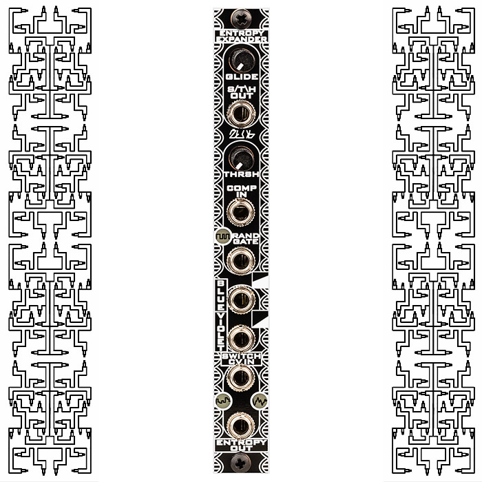
The Entropy Expander is a 3HP Analog Random Voltage Generator that expands upon the features of the Zlob Entropy Euroack Module.
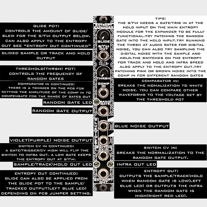
The Entropy with Expander together packs some of the most random voltage options in 6HP. It provides a controllable “Glide”(slew) out for the S/T\H, a comparator with a controllable rate(“Thrsh”) of random gates(“Rand Gate”) out with an input to compare other waveforms (Comp In, inserting a cable into here breaks the white noise normalisation), and high pass filtered white noise resulting in approximate “Blue noise”(+3db/octave) and “Violet noise”(+6db/octave) outs.
The unique part of the circuit is a voltage controlled A/B switch thats normalled to the “Rand Gate” out that’s switching between the S/T\H out (left Blue led window) and Infra out (right Red led window), the Glide control also effects the S/T\H coming out of the switch so you can get very random results from the “Entropy Out.” Inserting a cable into “Switch CV In” breaks the random gate normalisation and lets you toggle between A/B (left S/T\H out and right Infra out, indicated by the led windows) with your own gate or trigger.
There is a jumper on the PCB to select if you want glide on the s/t\h at, Entropy out, or un-slewed operation. There is also a trimmer for setting the amplitude of the incoming signal at “Comp In” which sets the frequency range of random gates. This may have to be adjusted depending on your Entropy version.
The random gate range can also be set up more as a noise oscillator by turning the PCB trimmer(clockwise) up or it can be set so the random gates are extremely slow(trim counter clockwise) with minutes between each random gate.
SEE ILLUSTRATED MANUAL IN THE IMAGE GALLERY
Entropy Expander – Build Document | Connecting the Entropy Expander guide
Specs:
- Width: 3HP
- Depth: 45mm or 1.75″
- Reverse Power Protected
- Current Consumption: +12v: 15mA, -12v: 10mA
- Ships with M3 black nylon screws
- Panel Material: PCB

